By Povilas Sindriūnas, AGACAD Architectural Engineer & BIM Application Engineer

In previous articles we have discussed how to create an In-Place Mass and Mass family and shown how to efficiently generate Revit elements upon massing. Now we’re going to take it one step further and demonstrate how to begin with a project concept and finish off with fully framed elements and drawings in less than 30 minutes using AGACAD’s Wood Framing Wall and Metal Framing Wall BIM Solutions.

At the outset, it’s important to set out your massing accordingly. The more details you have, the better. Sizing and number of levels is a good place to start sculpting volumes. Generally, volumetric massing is widely accepted as a primary means of early stage building design. Using mass blocks to define a building’s future shape, size, space quality, and design features is a standard method of tackling a new project at the conceptual design stage. Revit has a great tool for massing at a detailed level, i.e. a fixing (fastener) or a detail that is part of a larger assembly. It also works great with large-scale massing, i.e. clusters of buildings or an entire masterplan.
Ok, let’s do it. From concept to framing to drawings in under 30 minutes.
 |
 |
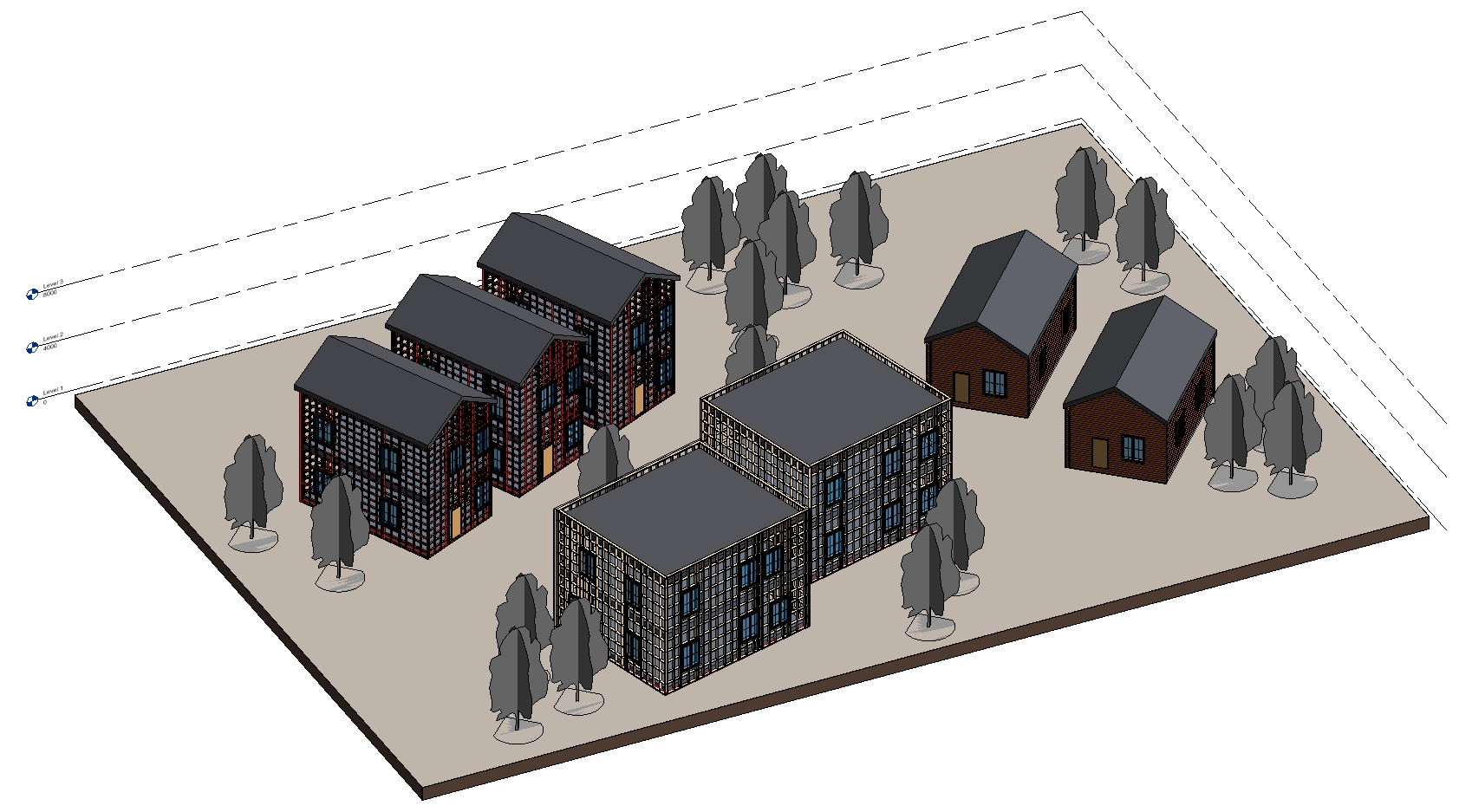
Create a new Revit project. Then begin the exercise by creating datum levels to represent the floor-to-floor heights. Use native Revit functionality. Once levels are established, model a few simple in-place masses. To do that, go to the ‘Massing & Site’ tab and select the ‘In-Place Mass’ tool. Then name your mass and start drawing 2D lines, which can later be turned into 3D masses using the ‘Create Form’ tool.
 |
 |
Once the volumes are in place, you can still edit them roughly using the grab handles or more precisely by going into the mass editor and using the drawing tools.
At this point you can add a roof and mass floors.

Then create Revit floors and walls by selecting the 3D mass surface.

 1. Defined Mass |
 2. Mass floors and roofs added |
 3. Floors generated from mass floors |
 4. Walls generated from mass face. Doors & windows also added. |
This type of workflow is ideal for digitally visualizing projects that are still at an early development stage or modeling an existing building with known dimensions and other features.
When massing and details like doors and windows are complete, the next step is to define the composition of walls. Then we’re going to link Revit walls to AGACAD’s Wall+ tool and define which framing configuration is going to be used for which types of wall layers. In this case we have two layers – a primary frame inner leaf and masonry brick outer leaf.
Here are some visuals retracing the above steps.
1. Provide information for wall types used in the project.⤵

2. Link Revit walls to Wall+ via Link Wall function.⤵

3. Use Frame Wall / Link Wall / Framing Configurations functions to set up the framing parameters.⤵

Once walls and confiugurations have been prepared, we can begin framing. First off, we’ll frame those two cabins via the ‘Build Log Wall’ function in the Wall+ menu.
 Select all walls and click ‘Build Log Wall’. |
 Wall+ will frame around doors & windows per predefined settings. |
The same workflow applies to all remaining walls in the project. To frame metal walls, select ‘Frame Wall’ in the Wall+M menu; for timber walls, use ‘Frame Wall’ in the Wall+ menu.
 Achieve highly accurate framing and detailing. |
 More layers can be generated for various wall types. |

Create unlimited configurations for different wall types.
When all walls have been framed, number all elements and start creating assemblies via ‘Create Assembly’ in the Wall+ menu. This way we produce not just assemblies but also auto-generate shop drawings with tags and dimensions in place.
So, to sum up, I’ve here shown an effective way to create massing and turn it into a fully framed model of multiple buildings with wall frames and shop drawings done automatically.

Revit elements built using in-place massing.
Wall frames created via predefined configurations using AGACAD Wall+ tool.
To find out more about how AGACAD’s Wood and Metal Framing Wall solutions can enhance your daily workflow of framing walls in Revit, watch our wall framing webinar (aired May 13, 2020). We also invite you to download our TOOLS4BIM Dock to take a FREE TRIAL of either our timber or steel framing Revit tools. And we encourage you to ask for a complimentary personal demonstration of the framing software with one of our BIM consultants. Just send us a note, and we’ll take it from there.


Subscribe to our BLOG newsletter and stay updated on upcoming free webinars, Revit tips & tricks, and the latest news on AGACAD TOOLS4BIM development and applications!


